
By Dr Subramanya Krishna Bhat
Amidst the current water crisis being witnessed globally, Rain Water Harvesting (RWH) could be our oasis in the desert
Almost all the water found on Earth’s surface (about 97.5%) is saltwater. Of the total water resources, only 0.007 percent of fresh water is available for human consumption. In such a scenario, rainwater harvesting is a sound solution.
We live in a time when every single drop of water matters. Now is the time to rethink our water management strategy by employing rain water harvesting: incorporating RWH into the way we think about the environment, by installing RWH facilities on developed sites as well as planning such facilities into the design and architecture of new buildings.
Essentials of Rain Water Harvesting
There are two commonly used types of RWH—the Direct Method and the Gravity Method. What RWH does is provide for a dependable water reserve for each home, building or campus. With the cost of construction of a rooftop RWH system being relatively low, and operation and maintenance being practically free of labour—RWH is a solid alternative. There are other advantages also: like reducing salt accumulation in the soil and averting offsite flooding. However, there are some factors that can be disadvantageous as well. For example, the success of the RWH depends on the frequency of rain and amount of rainfall. Likewise, the size of the facilities matter as well. There is leakage and contamination, which can be avoided—if the proper measures are taken. Finally, there is the extra cost involved if one is to install a RWH facility, but it is an investment that is worth it.
Elements of a RWH System
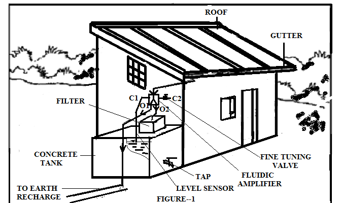
RWH system comprises four basic elements: a collection area, a conveyance system, ground recharge well and storage facilities. The collection area is the roof of a building. The effective roof area and the material used in constructing the roof influence the efficiency of collection and the water quality. A conveyance system consists of gutters and pipes that deliver rainwater falling on the rooftop to cisterns. The conveyances, roof surfaces and cisterns should be constructed of chemically inert materials, to avoid adverse effects on water quality.

FIGURE 1: Shows a schematic of a rooftop catchment system. Rainwater tank designs should include: a secure cover, an inlet filter, a manhole and drain to facilitate cleaning, an extraction system, a tap or pump, a sink away pit, a sediment trap and a sub-surface tank for livestock.
Filters
The contaminants need to be filtered before rainwater is stored in the tank. The filter system includes: sand bed filter, popup filter and stabilisation tank. It is to be noted that if foul flushing after a long dry spell or diverting the first part (during the first 8-10 minutes of rainfall) is not done, then the contaminants foul any type of filters.
Fluidics
National Fluid Power Association has defined fluidics as one in which sensing, controlling, information processing and logic operation are performed primarily through fluid dynamics, without the use of mechanical moving parts. Fluidic systems are similar to electronic systems in many ways. In the fluidic amplifiers, the flow of a high energy fluid jet (power jet) is controlled by a low energy fluid jet (control jet).
There are mainly five types of fluidic amplifiers and their classification is based upon the principle of operation. Monostable Fluidic Amplifier (MFA) is a wall attachment type amplifier used in a number of applications. MFA consists of a power chamber with a power nozzle, interaction zone, splitter, output ports O1and O2 and control ports C1 and C2. In this amplifier the power jet P will be attached to either of the boundary walls of O1or O2, till a signal is supplied at C1 or C2.
Methodology
The integration of the RWH system with MFA is done as shown in Figure 1. RWH system is built as per the requirement. MFA is installed as shown in the figure.
O2 is connected in between the foul flush and the filter of the storage tank pipe, and O1 is connected to the pipe carrying water to the ground recharge well.
C1 is connected to the bent pipe (level sensor). The level sensor tip should be exactly at the height of the water level required to be maintained in the storage tank.
C2 is open to the atmosphere via a valve (tuning MFA). MFA is designed to constrain P to be initially attached to the O2 boundary. A vacuum control signal is generated when the sensor`s tip within the tank is blocked by the free surface of the stored rainwater. This signal is used to switch the P from O2 to O1 to make the rainwater to flow into the soak away pit, till the level of the rainwater dips below the optimum level.
Working
The rainwater flows into the storage tank through the foul flush, MFA and the filter. The rainwater flows into MFA`s power chamber and issued as P in the interaction chamber. Since MFA is designed to make the P initially to be attached to the boundary on O2, P flows out of O2 into the tank.
As the tank is filled, the blocking the sensors` tip by the free surface generates vacuum signal and is conveyed C1. Due to this signal P switches to O1 and the rainwater flows to the soak away pit. When the water in the tank falls below the optimum level, it exposes the sensor`s tip to the atmosphere and stops the vacuum signal. Hence, automatically switches back to O2; facilitating rainwater to flow into the tank via filter till the optimum level is attained. Thus, by making only the required quantity of rainwater to flow through the filter, MFA reduces contamination deposited in the filter.
Maintaining RWH Facilities
Though the maintenance of a RWH facility is not too labour-intensive, a few things must be kept in mind:
- The foul flush should be cleaned after the first rains
- Fix an open screen at the entrance of MFA, which should be cleaned often
- MFA should be checked and its conduits should be cleaned
- Once the tank is full the filter can be cleaned and fitted into the system.
- Stored rainwater that will be used for drinking should be treated with appropriate purifying solution to eliminate microorganisms
In conclusion, the above-described is an innovative way of improving the life duration of a filter using RWH. By integrating the system with MFA, only the required quantity of water gets filtered. The excess rainwater is diverted to the soak away pit. This concept ensures a longer life of the filter and also less maintenance work. This innovative method is not only limited to a single storage tank but can be conveniently used in systems with multiple storage tanks.
The author has a PhD in Wind Energy and degrees in Law and Engineering. With 37 years of teaching experience, he is a permanent member of the Indian Society for Technical Education (ISTE), as well as, Fellow of the Institution of Engineers
This article was published in the April 2016 issue of Pure & Eco India
What is MFA,, for ground harvesting why filtration is required?
Is commercial MFA system available for RWH.Please share contact details